Gear Sensor Resistor Mod How-to
R3 GEAR SENSOR MOD HOW-TO
Here's the info on how to do the gear sensor resistor mod I have collected. Plenty of help and info came from many others, which I owe credit to!
This MOD should eliminate the 7% secondary butterfly restriction in gears 1,2, and 3 depending on the OEM tune in your bike.
To make this MOD switchable for the purpose of turning it on or off,
Here's the Parts/Tools I used:
Small 3 way toggle switch,
720-680 ohm 1/4-1/2 watt resistor,
18-22 gauge wire,
Shielded blade or bullet terminals,
Heat shrink, Electrical tape, Soldering gun, electrical grade solder, and flux,
Drill and drill bit large enough to make a hole for switch to fit through.
I really suggest that you have at least some basic skills in soldering. If not, practice on scrap test wire first. To solder wires right, the most important aspect of good soldering is you MUST have the wire and solder extremely clean. NO oil, or dirt and copper wire must be shiny. Then before heating up wire, apply plenty of flux. Flux has a small amount of a cleaser/acid that when heated boils away rest of dirt. Use plenty of flux as it helps "suck" the solder down into the wire.
Please Note: Anyone who has received an UPDATED OEM TUNE from Triumph which includes Anything other than the STOCK Classic, or STOCK Standard tune, might want to check if their 4th and 5th gear mapping restricts the secondary butterflies. Some of the Triumph Tunes for aftermarket exhaust and No cat or cat bypass restrict 4th and 5th gears also, which will nullify this MOD.
REMEMBER TO HAVE THE BIKE OFF, AND BATTERY DISCONNECTED BEFORE ATTEMPTING THIS MOD, OR CHECKING RESISTANCE!
"Originally Posted by ROB
Well I figured it out and I now have a switch I can flick to change between standard and the 4th gear tune.
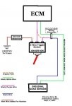
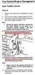
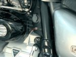
Undo the 2 screws where the accesory socket fits to get to the wiring harness. You will find many connectors back here, but you must follow the wiring up from the gear sensor to find the right connector. The correct one is the connector for the gear sensor (top one with 2 wires).
The black/white wire is the neutral light, leave this wire alone.
The other is a black wire that changes to black/purple at the wiring connector. (Black/Purple Wire Is The One To Cut)
The black/purple wire goes to the center terminal of a 3 pin switch.
The black wire goes to one side of switch.
The other side of switch goes thru a resistor then to frame(ground).
Resistor Values coming from OEM sensor are as follows:
1st Gear - 0.1k Ohm
2nd Gear - 0.2k Ohm
3rd Gear - 0.4k Ohm
4th Gear - 0.7k Ohm
5th Gear - 1.2k Ohm"
If you have a volt/OHM meter you can easily verifly you have the correct wire by unpluging the connector, and then testing the resistance from the Black wire in all the gears. Resistance will change instantly when you switch gears.
REMEMBER TO HAVE THE BIKE OFF, AND BATTERY DISCONNECTED BEFORE ATTEMPTING THIS MOD, OR CHECKING RESISTANCE!