
mstraub72
.040 Over
- Joined
- Sep 5, 2017
- Messages
- 82
- Location
- Leduc, Alberta, Canada
- Ride
- 2015 Triumph Rocket 3 Roadster ABS, Black & Red
Changing the tires on a 2015 R3R, the full walkthrough. Admin, feel free to move this to a more applicable spot if necessary, and anyone feel free to chime in with better ways to do any steps this amateur went with.
I just walked in from the garage after my first attempt at doing the tires on a R3R. My other bike is a Honda VFR800, with a single sided swing arm and a centre stand, so that one is easy, like taking a car wheel off. This one was intimidating. The forum was a huge help with things like how to jack the bike up safely, but I’m a little surprised that there isn’t a full walkthrough here I could find, or any good video’s online. Only found one from a 2010 R3T, and the way he did the rear tire seemed…not to the book. So, figured I’d type it all out while it’s fresh in the brain, and offer some tips the book missed.
Tools that you’ll need. 19mm socket for front axle, 14mm for rear, Torx bit to remove the single screw holding rear brake cable and ABS signal cable to the swingarm, and a few smaller metric allen keys or allen head sockets, 5mm for sure, wire brush or wire wheel for drill to clean old thread locker off bolts, and new threadlocker for reassembly. The blue, removable stuff, not the red permanent stuff. Some thin metal wire is handy to tie the calipers up to some part on the bike to keep the weight off the hoses as well. Grab whatever spline grease you prefer; I took the recommendation of the forum and got some Honda Moly 77 (updated version of legendary Moly 60). You’ll need some solvent to clean parts with as well; I just used lacquer thinner. Also, a normal hydraulic floor jack REALLY made placement of the rear tire back up into the bevel box easier. Apparently Triumph, in their infinite wisdom, doesn’t sell that plastic bit closest to the wheel (basically a seal, keeping grease in and gunk out) on the bevel box separately, so you break it, and it’s $2700 for a new entire bevel box. Dumb. I’d find someone with a 3D printer **** quick if I broke mine. Haha… Anyway, that floor jack was a godsend for this job, as that rear wheel is F’N HEAVY.
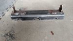
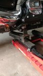
First up, I’ll leave it to you to decide how you want to jack the bike up. My crafty Dad with all the right tools knocked me out a quick bracket that simply mounts uprights outside those 8mm frame holes below the rear of the engine on each side of the bike (I understand older R3’s had larger holes there…13mm? Verify before crafting…), then spread the load by straddling one of the arms of a bike lift. I put thick rubber, that I normally use in my vice to protect softer materials, down on the other arm of the lift, and that spread the load a little over the more sensitive parts of the oil pan. Some people here just jack right up on the pan, but I felt this was a safer route. Total material cost to make the ghetto version of the Flipmeister bracket, $30 CDN for the ¼” wall box tube steel and a few grade 10 8mm bolts to act as pins.
This may have been overkill, but safety first when messing with 800lbs of bike I figure. I also tossed a couple ratchet straps up and over the bike, one over the seat, and one over the handlebar risers, and in a cross pattern, secured the bike to the jack. Did seem to make it more stable. Placebo effect, entirely possible. Haha…
So, another tip. Before jacking the bike off the ground, put some ratchet straps back to the backrest (if you have one) in a cross pattern from the handlebars, and gently pull them up snug. This will hold the forks in place when you have it airborne, making any sudden movements less likely, and makes working on the front tire more stable. If no backrest, hook it somewhere else, but not to your rear shocks. Stay tuned.
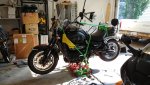
So, get her airborne. On one of those typical “ATV” jacks, I went up so the rear was about 8” to 12” off the ground. Most of these jacks have little safety detents that you can drop some lever into to lock the bike from falling if the hydraulics give out; I was in the middle safety notch of 3. The fore/aft tilt of the bike will vary depending on your balance on the stand (mine was a little front heavy, with the custom fabbed rear support being a little too tall in retrospect). Either way, you want a significant amount of clearance. Get the license plate off too…helps clear the tire.
First thing the book never mentions is that, bare minimum, your left exhaust pipe and mounting bracket is going to have to go. The book even shows the stupid exhaust in place as you “withdraw the wheel spindle”, aka the axle, making it look like it’ll clear under the pipe. But nope, unless I have some weird model year, the left exhaust and the black support bracket are directly in front of that 14mm axle head. Besides, having the exhaust off (I did both sides) sure made the rest of the job easier and less stressful about dinging up chrome. So, left side, I left the heat shield on, loosened up the clamp that holds the pipe to the Y pipe below the bike. Unsure what else to call that, but by “Y pipe”, I mean the splitter that diverts exhaust to each side of the bike. So, loosen that right up, undo the two 12mm bolts from the support bracket, and gently wiggle the exhaust off. Watch the front side of the chrome heat shield, you don’t have a lot of clearance while wiggling.
After that one is off, get the other side off. This side was easier to remove the heat shield, and that was simply loosening the pinch clamp at the rear of the shield, and the single 5mm allen bolt at the front. The clamp mechanism will be obvious when you have it off, it just falls into two pieces. When reinstalling, I just gently installed the 5mm allen bolt, and then reached the “back” piece of the clamp up and around, hooking it onto the top mating clip at the top of the backside of the shield, then replace screw and tighten up.
Next up, the right muffler. Loosen off the same clamp to the Y pipe below the bike, and then the two bolts holding the pipe to the support bracket. Wiggle and ease the pipe off the Y pipe. Set aside to avoid getting stepped on.
Now the support brackets. Their removal is the same on each side. One bolt holding it on is hidden behind the black trim piece behind your passenger pegs, so that trim has to go. Two allen heads at the front, and remove your passenger pegs. 12mm nut I believe. They’re happily notched on the back side, so no stress about trying to get them realigned perfectly. Behind the trim piece you will find your final bolt. 12 or 14mm…can’t remember right now. Take it out, and remove brackets. Set them aside and thread bolt back into bike a few turns for safe keeping. Helps avoid confusion later; I try and rethread every bolt I remove as I go along.
After those brackets are out of the way, next step was actually getting down to business removing the rear wheel. I slid my floor jack under the rear tire from the right side of the bike, knowing that eventually, I’m going to need to withdraw the wheel from the bevel box by pulling it that direction. I juuuuuust snuck up with the jack until you could see that it took up a little of the weight.
First up, the axle. Take a 24mm socket / wrench to the big nut on the right side of the axle. You’ll need a 14mm on the opposite side to resist the axle turning. Pop that nut off, and set aside. Next, you need to get the axle withdrawn enough to clear the swingarm and the rear brake caliper bracket. You really don’t want to mess the axle threads up, so if you need to get it started with a hammer, make sure you put a piece of wood against the face of the threaded axle to protect the threads, and gently tap it to get it going out the left side of the bevel box. There shouldn’t be much resistance at all, especially if you’ve got the tire supported by a floor jack, so if it’s fighting you, make sure you aren’t missing something.
So, gently withdraw the axle until you clear the brake mounting bracket. To remove the bracket, you also need to remove one more bolt towards the front of the bike. The front bolt is called a “torque reaction bolt”, and the manual says to replace after removing. The boys at my dealership just smirked when I asked them about it as I was dropping my wheels off for new skins, and said, nah, just clean off the old thread lock and put it back. So, your call…get a new one to follow the manual to spec, or clean off the threads and relock with removable locktite when reinstalling later.
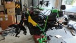
Here’s where the manual wasn’t very helpful again. As I managed to get the caliper bracket loose after withdrawing the axle and removing the torque reaction bolt mentioned above, I found that there is very little room to get the whole assembly safely tied up with steel wire, up and out of the way. On mine, the brake line and ABS signal cable were held down quite tightly with a single Torx headed screw and rubber pinch clamp, screwed to the swingarm. Now, I had the right Torx bit, but I couldn’t get at that dumb screw no matter what I did. The rear right shock was in the way. Sooooo, off comes THAT too. The bike was getting very naked at this point. Was surprisingly easy, just undo the top and bottom shock mount bolts, 12 or 14mm, and the shock slid off with little excitement. I don’t know if I was expecting it to spring open a little like a car spring, but it just pulled off smoothly. Make a note of which bolt and washer goes where, one is a huge washer, one smaller. Think the big washer was on top if memory serves, but it’s fairly apparent when reinstalling. So, get the shock out of the way, undo the Torx screw holding the rear brake hose down, and now you have a lot more freedom to tie the entire rear brake bracket assembly up and out of the way without kinking any lines.
Pt 2 to follow, 10000 char maximum apparently...
I just walked in from the garage after my first attempt at doing the tires on a R3R. My other bike is a Honda VFR800, with a single sided swing arm and a centre stand, so that one is easy, like taking a car wheel off. This one was intimidating. The forum was a huge help with things like how to jack the bike up safely, but I’m a little surprised that there isn’t a full walkthrough here I could find, or any good video’s online. Only found one from a 2010 R3T, and the way he did the rear tire seemed…not to the book. So, figured I’d type it all out while it’s fresh in the brain, and offer some tips the book missed.
Tools that you’ll need. 19mm socket for front axle, 14mm for rear, Torx bit to remove the single screw holding rear brake cable and ABS signal cable to the swingarm, and a few smaller metric allen keys or allen head sockets, 5mm for sure, wire brush or wire wheel for drill to clean old thread locker off bolts, and new threadlocker for reassembly. The blue, removable stuff, not the red permanent stuff. Some thin metal wire is handy to tie the calipers up to some part on the bike to keep the weight off the hoses as well. Grab whatever spline grease you prefer; I took the recommendation of the forum and got some Honda Moly 77 (updated version of legendary Moly 60). You’ll need some solvent to clean parts with as well; I just used lacquer thinner. Also, a normal hydraulic floor jack REALLY made placement of the rear tire back up into the bevel box easier. Apparently Triumph, in their infinite wisdom, doesn’t sell that plastic bit closest to the wheel (basically a seal, keeping grease in and gunk out) on the bevel box separately, so you break it, and it’s $2700 for a new entire bevel box. Dumb. I’d find someone with a 3D printer **** quick if I broke mine. Haha… Anyway, that floor jack was a godsend for this job, as that rear wheel is F’N HEAVY.
First up, I’ll leave it to you to decide how you want to jack the bike up. My crafty Dad with all the right tools knocked me out a quick bracket that simply mounts uprights outside those 8mm frame holes below the rear of the engine on each side of the bike (I understand older R3’s had larger holes there…13mm? Verify before crafting…), then spread the load by straddling one of the arms of a bike lift. I put thick rubber, that I normally use in my vice to protect softer materials, down on the other arm of the lift, and that spread the load a little over the more sensitive parts of the oil pan. Some people here just jack right up on the pan, but I felt this was a safer route. Total material cost to make the ghetto version of the Flipmeister bracket, $30 CDN for the ¼” wall box tube steel and a few grade 10 8mm bolts to act as pins.
This may have been overkill, but safety first when messing with 800lbs of bike I figure. I also tossed a couple ratchet straps up and over the bike, one over the seat, and one over the handlebar risers, and in a cross pattern, secured the bike to the jack. Did seem to make it more stable. Placebo effect, entirely possible. Haha…
So, another tip. Before jacking the bike off the ground, put some ratchet straps back to the backrest (if you have one) in a cross pattern from the handlebars, and gently pull them up snug. This will hold the forks in place when you have it airborne, making any sudden movements less likely, and makes working on the front tire more stable. If no backrest, hook it somewhere else, but not to your rear shocks. Stay tuned.
So, get her airborne. On one of those typical “ATV” jacks, I went up so the rear was about 8” to 12” off the ground. Most of these jacks have little safety detents that you can drop some lever into to lock the bike from falling if the hydraulics give out; I was in the middle safety notch of 3. The fore/aft tilt of the bike will vary depending on your balance on the stand (mine was a little front heavy, with the custom fabbed rear support being a little too tall in retrospect). Either way, you want a significant amount of clearance. Get the license plate off too…helps clear the tire.
First thing the book never mentions is that, bare minimum, your left exhaust pipe and mounting bracket is going to have to go. The book even shows the stupid exhaust in place as you “withdraw the wheel spindle”, aka the axle, making it look like it’ll clear under the pipe. But nope, unless I have some weird model year, the left exhaust and the black support bracket are directly in front of that 14mm axle head. Besides, having the exhaust off (I did both sides) sure made the rest of the job easier and less stressful about dinging up chrome. So, left side, I left the heat shield on, loosened up the clamp that holds the pipe to the Y pipe below the bike. Unsure what else to call that, but by “Y pipe”, I mean the splitter that diverts exhaust to each side of the bike. So, loosen that right up, undo the two 12mm bolts from the support bracket, and gently wiggle the exhaust off. Watch the front side of the chrome heat shield, you don’t have a lot of clearance while wiggling.
After that one is off, get the other side off. This side was easier to remove the heat shield, and that was simply loosening the pinch clamp at the rear of the shield, and the single 5mm allen bolt at the front. The clamp mechanism will be obvious when you have it off, it just falls into two pieces. When reinstalling, I just gently installed the 5mm allen bolt, and then reached the “back” piece of the clamp up and around, hooking it onto the top mating clip at the top of the backside of the shield, then replace screw and tighten up.
Next up, the right muffler. Loosen off the same clamp to the Y pipe below the bike, and then the two bolts holding the pipe to the support bracket. Wiggle and ease the pipe off the Y pipe. Set aside to avoid getting stepped on.
Now the support brackets. Their removal is the same on each side. One bolt holding it on is hidden behind the black trim piece behind your passenger pegs, so that trim has to go. Two allen heads at the front, and remove your passenger pegs. 12mm nut I believe. They’re happily notched on the back side, so no stress about trying to get them realigned perfectly. Behind the trim piece you will find your final bolt. 12 or 14mm…can’t remember right now. Take it out, and remove brackets. Set them aside and thread bolt back into bike a few turns for safe keeping. Helps avoid confusion later; I try and rethread every bolt I remove as I go along.
After those brackets are out of the way, next step was actually getting down to business removing the rear wheel. I slid my floor jack under the rear tire from the right side of the bike, knowing that eventually, I’m going to need to withdraw the wheel from the bevel box by pulling it that direction. I juuuuuust snuck up with the jack until you could see that it took up a little of the weight.
First up, the axle. Take a 24mm socket / wrench to the big nut on the right side of the axle. You’ll need a 14mm on the opposite side to resist the axle turning. Pop that nut off, and set aside. Next, you need to get the axle withdrawn enough to clear the swingarm and the rear brake caliper bracket. You really don’t want to mess the axle threads up, so if you need to get it started with a hammer, make sure you put a piece of wood against the face of the threaded axle to protect the threads, and gently tap it to get it going out the left side of the bevel box. There shouldn’t be much resistance at all, especially if you’ve got the tire supported by a floor jack, so if it’s fighting you, make sure you aren’t missing something.
So, gently withdraw the axle until you clear the brake mounting bracket. To remove the bracket, you also need to remove one more bolt towards the front of the bike. The front bolt is called a “torque reaction bolt”, and the manual says to replace after removing. The boys at my dealership just smirked when I asked them about it as I was dropping my wheels off for new skins, and said, nah, just clean off the old thread lock and put it back. So, your call…get a new one to follow the manual to spec, or clean off the threads and relock with removable locktite when reinstalling later.
Here’s where the manual wasn’t very helpful again. As I managed to get the caliper bracket loose after withdrawing the axle and removing the torque reaction bolt mentioned above, I found that there is very little room to get the whole assembly safely tied up with steel wire, up and out of the way. On mine, the brake line and ABS signal cable were held down quite tightly with a single Torx headed screw and rubber pinch clamp, screwed to the swingarm. Now, I had the right Torx bit, but I couldn’t get at that dumb screw no matter what I did. The rear right shock was in the way. Sooooo, off comes THAT too. The bike was getting very naked at this point. Was surprisingly easy, just undo the top and bottom shock mount bolts, 12 or 14mm, and the shock slid off with little excitement. I don’t know if I was expecting it to spring open a little like a car spring, but it just pulled off smoothly. Make a note of which bolt and washer goes where, one is a huge washer, one smaller. Think the big washer was on top if memory serves, but it’s fairly apparent when reinstalling. So, get the shock out of the way, undo the Torx screw holding the rear brake hose down, and now you have a lot more freedom to tie the entire rear brake bracket assembly up and out of the way without kinking any lines.
Pt 2 to follow, 10000 char maximum apparently...
") Can't seem to attach a PDF here using the Upload A File link, but if the Admin or anyone else wants to tell me how, I'll upload away! Thanks all for the kind words; once I get a coffee in me and a laptop, all the typing classes from back in high school kick in. Haha....
Can't seem to attach a PDF here using the Upload A File link, but if the Admin or anyone else wants to tell me how, I'll upload away! Thanks all for the kind words; once I get a coffee in me and a laptop, all the typing classes from back in high school kick in. Haha....