Bad Voltage Regulator ...OR?

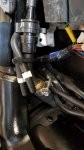
I observed that Triumph didn't have to shoehorn the unit in the trapezoid made by the vertical back of the engine block forward, the slope of the rear fender, the backward slant of the left side frame member, and drive shaft below. That said, the space is limited, and putting the new unit on top of the existing bracket didn't fit, and would involve relocating the tip-over switch (which will probably have to be done anyway).

And the existing bracket is welded to the frame, so this will not be a simple unbolt old, bolt in new proposition.

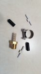
Well @Joesmoe, I removed the canister today. Here is what I used for people who might be interested.

2 Plastic 1/8" barbed connectors
2 1/8" Vacuum caps
1 3/16" barb connector to a 1/4" Male Pipe Thread
1 16-18mmm stainless steel fuel line hose clamp.

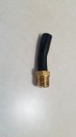
I found that the ID of the two vacuum hoses were a snug 1/8". Using anything bigger will cause the hoses and caps to crack over time. I cut the rollover valve line long enough to insert a 3/16" barb fully but still left the part of the hose that originally fit on the bottom rollover valve. In doing so, you can insert a 1/4" pipe thread in the opening that is left in the hose that drops down below from the canister. That hose opening at the top is around 1/2". The 3/16" barb to 1/4" Male Pipe thread worked perfect for hooking things up for the rollover valve and drain tube.

I originally put some teflon tape on the pipe thread, but the tape was so slick it caused the hose to creep down in the tapered 1/4" male pipe thread when the clamp was tightened. Good plan but it didn't work. Clamp directly on the threads as it will hold and seal just fine.

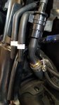
A little tape on the purge connector for now and a few plastic ties and I'm ready to go.

The rectifier will be another issue for fitment. I'll have to figure that out when I get it.
 

Attachments

  • 20180508_144922.jpg
    20180508_144922.jpg
    133 KB · Views: 16
  • 20180508_152348.jpg
    20180508_152348.jpg
    110.7 KB · Views: 20
  • 20180508_145947.jpg
    20180508_145947.jpg
    210.7 KB · Views: 18
  • 20180508_153427.jpg
    20180508_153427.jpg
    165.3 KB · Views: 18
You put the RR vertically where the canister went....mounting it.....that's the custom bit.....but the screw hole for the canister bracket should give you ideas for a strap with some way to fix it in place on the bottom end. That's where my mind is heading and with the right material it will be stupid simple, so I doubt there's be a market.
 
The vacuum lines are connected. Saved me having to plug them, and figuring out what went where.

There is still the vent line from the tank that like many thousands of other bikes, is simply led down.

Thanks Paul, I just got my shingadingy R/R after reading all this stuff and wasn't crazy about undoing the spaghetti of hoses under there but now I think I'll get the cutters and have at it.
 
I like the idea of freeing up the area where the canister went, by putting the R/R back where it belongs.

Well Paul, I Got the new R/R....I can't see it going back where it belongs...ya can't put a square peg in a round hole or a size 11 foot in a size 8 shoe. Working on a mounting solution where you currently have appears to be the most logical location. My current plan is to add some additional heatsinks to the aluminum backing plate I made. In my opinion, it should be mounted to a more heat dissipating surface. A couple more days of trial and error with the brackets and I hope to have some pictures. Making a one of a kind isn't too bad to do, but trying to be able to acurately duplicate it with the primitive tooling I have is way more difficult. Very very time consuming and labor intensive getting a good prototype.
 
Last edited:
... My current plan is to add some additional heatsinks to the aluminum backing plate I made. In my opinion, it should be mounted to a more heat dissipating surface. ...

I wouldn't worry about adding much more heatsink capability - that's already a pretty massive heatsink with a lot of surface area through the fins.
Ideally I'd prefer to see it mounted rotated 90 deg (if possible) vs those already pictured, just to improve airflow between the fins as opposed to just over them; but I don't think it's a problem as already illustrated however.
The Unit will dissipate 'some' heat, a little more than the OEM MOSFET Shunt type, but nothing like as much as an old-school SCR Shunt R/R. Nothing that should really cause it to self-destruct.

True...I saw it wasn't running excessively hot and it should be fine, but I thought I would take advantage of all that metal plate surface area on the back of the R/R. The existing heatsink on the device is quite generous. With airflow being a little less I suspect in the new mounting area as opposed to the original location and since I have the space to do it I figured..what the heck, let's add a few of these on the back side of my mounting plate. I have used these before on a couple other projects and they are the perfect size...100x25x10mm. Easily drilled and mounted. What can I say, sometimes I'm my own worst enemy on overkill and being fussy! After reading many of your posts over several years @DEcosse, I suspect you suffer from the same condition of being fussy. :rolleyes:
 

Attachments

  • Screenshot_20180512-075617_Amazon Shopping.jpg
    Screenshot_20180512-075617_Amazon Shopping.jpg
    42.4 KB · Views: 3
I still want to put the R/R back in the original location. All it takes is . . . the right application of force.

I'm totally unwilling to tear my bike apart that much to make it fit. That space under the side cover isn't that important to me. The footprint of the regulator is just too big in my opinion. Plus, if I want, I can leave the old one in place as spare if I can adequately cover the electronics.
 
Last edited:
Back
Top