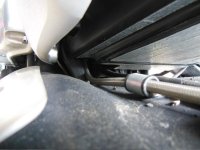
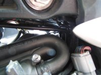
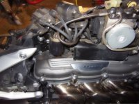
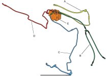
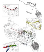
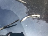
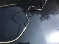
I replaced the rear brake line with a one piece hose made to order by HEL performance. With this opportunity I replaced all aluminium washers with new ones. Compound metal/rubber washers on ABS banjos and freshly annealed copper washers on the rear caliper. The brake hose was ordered a little too long so I twisted it around frame a little. I drew blood out if it yesterday and it holds well. Before I could feel it fading from a day to another. So I put on hold honing and servicing master cylinder for a while. Time will tell. The design still has a weakness with the two columns of fluid in front and rear hose having negative static pressure and having tendency to flow down to the master cylinder which is the lowest component of the system. If it still draws air over time I will check the cups of the caliper as Turbo200R4 says and maybe experiment with an external reservoir behind the radiator to add an additional column of fluid to compensate negative pressure in the installation. Next step would be for sure to replace all OEM lines with custom built ones since I had enough with Triumph ones. Thinking about Goodridge 600 series, the winter is long enough and it’s a pity to keep the toolboxes closed.