
Bedifferent
Old man on a bike
I have been continuing to make modifications to my R3T over the winter since I can't ride it and the weather sucks! My cargo trailer leaves me just enough room to work and a small heater makes for a decent working temperature and environment.
Anyway, there has been a lot of discussion about the inadequate size of the ground wire on the rocket and many people have changed it out to help improve starting. You don't need to replace the wire if you don't want to and I consider doing so to be a waste of time. All you need to do is add a 6 gage wire to the battery negative terminal and ground it to the chassis. This will add up to 70 amps of current carrying capacity from your negative battery terminal to chassis ground. It is foolish to think just because your not grounding directly to the engine that your not adding more capacity with the extra wire. Adding the jumper wire will exceed the ground current capacity that you might get if you changed your existing single ground wire to a 2 gage ground wire.
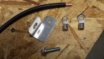
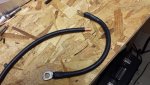
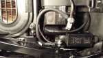
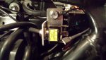
I have included some pictures of what I did to achieve this on my rocket. My wire jumper is crimped, soldered, covered with heat shrink tubing and the terminal were oriented for easy installation. I never do just crimped connections! I removed any paint from my ground point and use toothed/star washers and dielectric grease to maintain the integrity of the connections. I replaced the chassis mounting screw with a longer length so I could add a bracket on the opposite end under the left side cover for mounting a 30 amp toggle switch should I ever need to bypass a bad ignition switch. I have already made a fused harness that simply plugs into the fuse box. The terminals from my harness simply plug into the switch for turning my ignition on and off with easy access. I have shown the switch attached to the bracket and the extra wire showing next to it is a ground connection for the switch as the tip is illuminated with an LED. My switch will not be installed, unless I need it, as there is no point in exposing it to the weather until needed....if ever.
FYI......I just installed the Eastern Beaver Relay Kit this past weekend, but I have a word of advice for anyone ordering the kit. The stock H4 light socket on my rocket has the terminals exposed on the back side of the socket. My advice would be to order one of the H4 sockets from Easter Beaver that has a closed back that covers the plug terminals. You don't want to have any exposed connections floating around inside your headlight shell no matter how remote the chance is they will short out. Electrical tape is not an option for me so I'm changing my plug to the closed back style as soon as the parts arrives.
Please Note: DEcosse has made some interesting points later in this thread about adding this connection and I have also made some additional comments to his post as well. Read it all over and make an informed decision should you decide to add the wire. Things are never simple.
Anyway, there has been a lot of discussion about the inadequate size of the ground wire on the rocket and many people have changed it out to help improve starting. You don't need to replace the wire if you don't want to and I consider doing so to be a waste of time. All you need to do is add a 6 gage wire to the battery negative terminal and ground it to the chassis. This will add up to 70 amps of current carrying capacity from your negative battery terminal to chassis ground. It is foolish to think just because your not grounding directly to the engine that your not adding more capacity with the extra wire. Adding the jumper wire will exceed the ground current capacity that you might get if you changed your existing single ground wire to a 2 gage ground wire.
I have included some pictures of what I did to achieve this on my rocket. My wire jumper is crimped, soldered, covered with heat shrink tubing and the terminal were oriented for easy installation. I never do just crimped connections! I removed any paint from my ground point and use toothed/star washers and dielectric grease to maintain the integrity of the connections. I replaced the chassis mounting screw with a longer length so I could add a bracket on the opposite end under the left side cover for mounting a 30 amp toggle switch should I ever need to bypass a bad ignition switch. I have already made a fused harness that simply plugs into the fuse box. The terminals from my harness simply plug into the switch for turning my ignition on and off with easy access. I have shown the switch attached to the bracket and the extra wire showing next to it is a ground connection for the switch as the tip is illuminated with an LED. My switch will not be installed, unless I need it, as there is no point in exposing it to the weather until needed....if ever.
FYI......I just installed the Eastern Beaver Relay Kit this past weekend, but I have a word of advice for anyone ordering the kit. The stock H4 light socket on my rocket has the terminals exposed on the back side of the socket. My advice would be to order one of the H4 sockets from Easter Beaver that has a closed back that covers the plug terminals. You don't want to have any exposed connections floating around inside your headlight shell no matter how remote the chance is they will short out. Electrical tape is not an option for me so I'm changing my plug to the closed back style as soon as the parts arrives.
Please Note: DEcosse has made some interesting points later in this thread about adding this connection and I have also made some additional comments to his post as well. Read it all over and make an informed decision should you decide to add the wire. Things are never simple.
Attachments
Last edited:
