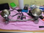
cr0ft
Living Legend
Last year I picked up a set of three JW Speaker LED reflectors for the front and it was a considerable upgrade in light output and looks even.
Which made me that much more aware of the other incandescents that littered the bike.
So, this year I decided I would complete the job and do a full conversion. Everything that makes light on the bike should be LED.
So, the parts list I went with.
From Superbrightleds.com:
- Tail light, Model 1157-R26-CBT, 1157 CAN Bus LED Bulb - Dual Function 26 SMD LED Tower - BAY15D Retrofit | LED Brake Light, Turn Light and Tail Light Bulbs | LED Car Light Bulbs | Super Bright LEDs
The tail light may be replaced later on with something more aggressive, which will be an easy job since it's not modded in any way.
- License plate light, WLED-NWHP5, 194 LED Bulb - 5 SMD LED Tower - Miniature Wedge Retrofit | Miniature Wedge Base LEDs | LED Car Light Bulbs | Super Bright LEDs
From Custom Dynamics.com:
- Rear indicators + tail/brake light halo, 48 LED GEN180AR2, "Dynamic Clusters2". Motorcycle LED Light Bulbs
- Front indicators + white halo, 48 LED GEN185CLUSTER, "Dynamic Ringz", same page as above.
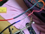
The Custom Dynamics product comes in an 1156 base (or rather with an 1156 pigtail) but since I was going to have to do some wire surgery anyway because both products had extra leads to do halos, I went with hardwired versions that have no pigtail, just a bunch of wires sticking out.
Other parts needed:
- 2 10 ohm, 25 watt resistors to equalize the load for the indicators. The Touring has self-canceling turn signals, and there's no easy relay replacement here as on other Rockets. But, self-cancelling, also not on the other rockets... Shoutout here to @DEcosse for helping me sort out what I needed to do here!
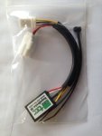
- Supabrake 3 brake light modulator; SupaBrake-3 TRIUMPH These come with the right connectors and it's a 30 second job to add modulators. Pricey, but very programmable and all in all very clever with timeouts when you brake more often etc. Recommended extra. You may be able to get a 15% discount with the code "dafobra15"... if you act before July 2016. See
!
That's the Supabrake 2, there's now a 3.
- Tons of heat shrink tubing in various sizes.
- Extra electrical wire for splicing.
- Some Posilocks and multiple Positaps to tap into the original wires.
And assorted odds and ends.
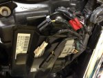
Step 1: Disconnect the rear harness from the front harness. The connectors are on the right-hand side.
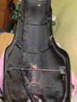
Step 2: disassemble and remove the entire rear fender.
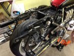
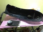
(Some stealthy black reflective tape came in around this time and is awaiting install).
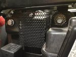
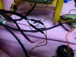
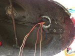
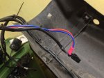
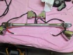
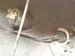
The tail light and the wires to the indicators and license plate light under the fender looks like this. The closest place to the indicators to get at tail/brake light wires is here - but not advisable to compromise them here, this is the filthiest wettest part of the entire bike. Not a great place to compromise wiring. So I had to go further up the bike and extend wires to do it.
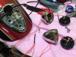
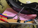
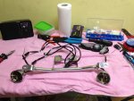
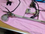
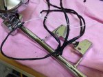
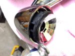
Rear indicator assembly unbolted and beginning further disassembly
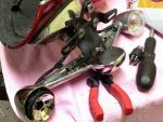
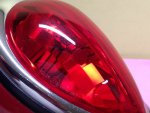
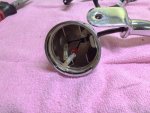
Reflector pulled out of the housing (it's rubber and just wedged in there - insert needlenose pliers carefully into the little holes by the lamp socket and wiggle it out.)
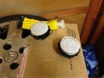
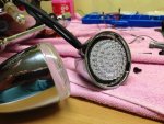
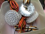
Dynamic clusters, two varieties (front/back)
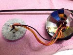
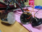
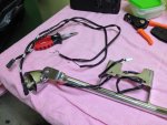
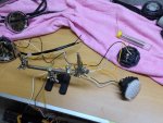
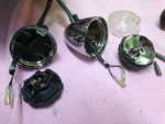
Indicators opened, cables pulled out for work.
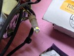
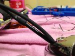
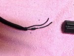
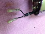
Black/silver cables. On both of them. Good luck figuring out which is positive and negative. Triumph cutting corners and not carrying through proper color coding. As I did not know this beforehand, I eventually had to reconnect these to the bike and measure it out with a multimeter.
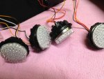
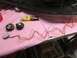
Rear clusters, ready to do some gluing. Clear silicone was used to glue the clusters straight onto the lenses. Note the four wires here - black/orange is indicators, and the two red shades are tail light and brake light, respectively. This is why this was so much work - getting power to those two red ones.
Contd.
Which made me that much more aware of the other incandescents that littered the bike.
So, this year I decided I would complete the job and do a full conversion. Everything that makes light on the bike should be LED.
So, the parts list I went with.
From Superbrightleds.com:
- Tail light, Model 1157-R26-CBT, 1157 CAN Bus LED Bulb - Dual Function 26 SMD LED Tower - BAY15D Retrofit | LED Brake Light, Turn Light and Tail Light Bulbs | LED Car Light Bulbs | Super Bright LEDs
The tail light may be replaced later on with something more aggressive, which will be an easy job since it's not modded in any way.
- License plate light, WLED-NWHP5, 194 LED Bulb - 5 SMD LED Tower - Miniature Wedge Retrofit | Miniature Wedge Base LEDs | LED Car Light Bulbs | Super Bright LEDs
From Custom Dynamics.com:
- Rear indicators + tail/brake light halo, 48 LED GEN180AR2, "Dynamic Clusters2". Motorcycle LED Light Bulbs
- Front indicators + white halo, 48 LED GEN185CLUSTER, "Dynamic Ringz", same page as above.
The Custom Dynamics product comes in an 1156 base (or rather with an 1156 pigtail) but since I was going to have to do some wire surgery anyway because both products had extra leads to do halos, I went with hardwired versions that have no pigtail, just a bunch of wires sticking out.
Other parts needed:
- 2 10 ohm, 25 watt resistors to equalize the load for the indicators. The Touring has self-canceling turn signals, and there's no easy relay replacement here as on other Rockets. But, self-cancelling, also not on the other rockets... Shoutout here to @DEcosse for helping me sort out what I needed to do here!
- Supabrake 3 brake light modulator; SupaBrake-3 TRIUMPH These come with the right connectors and it's a 30 second job to add modulators. Pricey, but very programmable and all in all very clever with timeouts when you brake more often etc. Recommended extra. You may be able to get a 15% discount with the code "dafobra15"... if you act before July 2016. See
That's the Supabrake 2, there's now a 3.
- Tons of heat shrink tubing in various sizes.
- Extra electrical wire for splicing.
- Some Posilocks and multiple Positaps to tap into the original wires.
And assorted odds and ends.
Step 1: Disconnect the rear harness from the front harness. The connectors are on the right-hand side.

Step 2: disassemble and remove the entire rear fender.


(Some stealthy black reflective tape came in around this time and is awaiting install).
The tail light and the wires to the indicators and license plate light under the fender looks like this. The closest place to the indicators to get at tail/brake light wires is here - but not advisable to compromise them here, this is the filthiest wettest part of the entire bike. Not a great place to compromise wiring. So I had to go further up the bike and extend wires to do it.

Rear indicator assembly unbolted and beginning further disassembly

Reflector pulled out of the housing (it's rubber and just wedged in there - insert needlenose pliers carefully into the little holes by the lamp socket and wiggle it out.)

Dynamic clusters, two varieties (front/back)

Indicators opened, cables pulled out for work.

Black/silver cables. On both of them. Good luck figuring out which is positive and negative. Triumph cutting corners and not carrying through proper color coding. As I did not know this beforehand, I eventually had to reconnect these to the bike and measure it out with a multimeter.

Rear clusters, ready to do some gluing. Clear silicone was used to glue the clusters straight onto the lenses. Note the four wires here - black/orange is indicators, and the two red shades are tail light and brake light, respectively. This is why this was so much work - getting power to those two red ones.

Contd.
Last edited:

