barbagris
Mad Scientist
- Joined
- Aug 1, 2010
- Messages
- 12,988
- Location
- On the verge of insanity
- Ride
- 1979 Guzzi V1000G5 - 2018 KTM 790 Duke
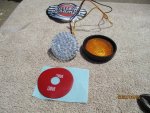
A proper indicator LED conversion.
This is just the idea and concept. I did this for my 2009 and I did make two other unfinished sets which went to Roadster owners. But I don't honestly know if they were ever fitted.
Really it's not hard to do, but you need some basic soldering and wiring skills. Yeah! - OK you need to be pretty handy at making stuff too.
I freely confess I cheated and had the basic Aluminium discs laser cut. They are 2mm thick and 55.3mm diameter.
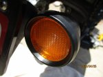
This a a perfect fit. They replace the original reflectors and bulb holders.
This is a write up of the plates/LEDs for REAR indicators. I never actually made a finished front pair - as I have custom made front units I made from a rear set.
Photos later.
For the rear plates you first need 2 holes for the lens screws. One of these (the inboard one - B) is a 3mm clearance hole. The other one (A) has to be tapped M3 and you will need to source a new M3 screw to fit. These are drilled at 180° at 47.5mm spacing (23,75 mm radius) - The front woud require both to be threaded M3 and requires a bit of machining/filing as they are push and twist fittings.
The other holes on my plates are 3mm and 8mm clearance.
The 3mm (C) are to attach the LED - I used 3mm self-tapping screws salvaged fron computer hard discs - These cut nicely into the aluminium plates on the LEDS - screwed on from the rear - use thermal transfer paste between LEDs and backplates. The spacing between the holes is to match those in the LED - these had 16mm spacing - I believe this is an industry standard - but check. I forgot the offset from centre - I drilled them radially and can't find the plans. It's just geometry.
The 8mm (D) is not critical - it's just to feed wires through.
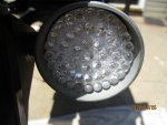
The LEDs are marked + and - . Self explanitary!. These are 10W LEDs and a 3*3 array. Rated at 12V - so no extra electronics required. Not on intermitent operation anyhow. You will need a load independant flasher relay (so "T" owners may need to do some R&D)
Like this the indicators will flash correctly - but the shared (left/right) dash light on pre-roadsters will not blink - on when active; off when not, but no blinking. To get the dash light to blink, you need to bridge one LED each side with a tiny resistor. This MAY not be necesary on Roadsters which have a dash light for each side. I did this in the custom front set.
It is possible - just, to get two LEDs on each plate. My rear pair have an orange and a red. The RED operates via an independant timed flasher that is activated by the brake circuit - Having them on full time WILL overheat the plate (I have tried) - so if you wanted running lights I would NOT recommend any more than 2W. To be honest I don't really recommend doing it as the Indicator lenses work best if the LED is 100% centrally mounted on the plate.
Some Spares as yet not made up.

This was an R&D pair - note the notching for the front - and weird wire drillings.

Final


This is just the idea and concept. I did this for my 2009 and I did make two other unfinished sets which went to Roadster owners. But I don't honestly know if they were ever fitted.
Really it's not hard to do, but you need some basic soldering and wiring skills. Yeah! - OK you need to be pretty handy at making stuff too.
I freely confess I cheated and had the basic Aluminium discs laser cut. They are 2mm thick and 55.3mm diameter.
This a a perfect fit. They replace the original reflectors and bulb holders.
This is a write up of the plates/LEDs for REAR indicators. I never actually made a finished front pair - as I have custom made front units I made from a rear set.
Photos later.
For the rear plates you first need 2 holes for the lens screws. One of these (the inboard one - B) is a 3mm clearance hole. The other one (A) has to be tapped M3 and you will need to source a new M3 screw to fit. These are drilled at 180° at 47.5mm spacing (23,75 mm radius) - The front woud require both to be threaded M3 and requires a bit of machining/filing as they are push and twist fittings.
The other holes on my plates are 3mm and 8mm clearance.
The 3mm (C) are to attach the LED - I used 3mm self-tapping screws salvaged fron computer hard discs - These cut nicely into the aluminium plates on the LEDS - screwed on from the rear - use thermal transfer paste between LEDs and backplates. The spacing between the holes is to match those in the LED - these had 16mm spacing - I believe this is an industry standard - but check. I forgot the offset from centre - I drilled them radially and can't find the plans. It's just geometry.
The 8mm (D) is not critical - it's just to feed wires through.
The LEDs are marked + and - . Self explanitary!. These are 10W LEDs and a 3*3 array. Rated at 12V - so no extra electronics required. Not on intermitent operation anyhow. You will need a load independant flasher relay (so "T" owners may need to do some R&D)
Like this the indicators will flash correctly - but the shared (left/right) dash light on pre-roadsters will not blink - on when active; off when not, but no blinking. To get the dash light to blink, you need to bridge one LED each side with a tiny resistor. This MAY not be necesary on Roadsters which have a dash light for each side. I did this in the custom front set.
It is possible - just, to get two LEDs on each plate. My rear pair have an orange and a red. The RED operates via an independant timed flasher that is activated by the brake circuit - Having them on full time WILL overheat the plate (I have tried) - so if you wanted running lights I would NOT recommend any more than 2W. To be honest I don't really recommend doing it as the Indicator lenses work best if the LED is 100% centrally mounted on the plate.
Some Spares as yet not made up.
This was an R&D pair - note the notching for the front - and weird wire drillings.
Final


